
Hebesysteme
U-Konfiguration
CAD & Broschüren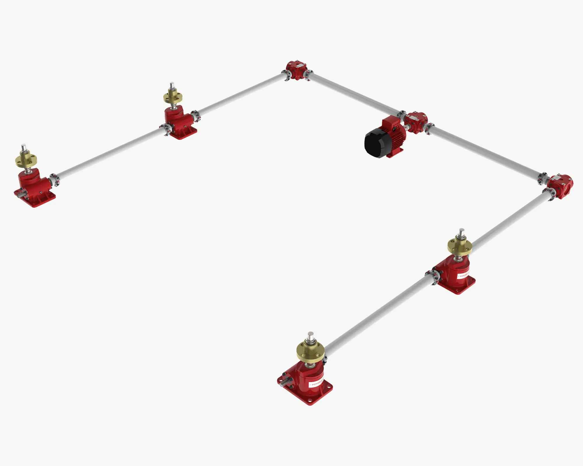
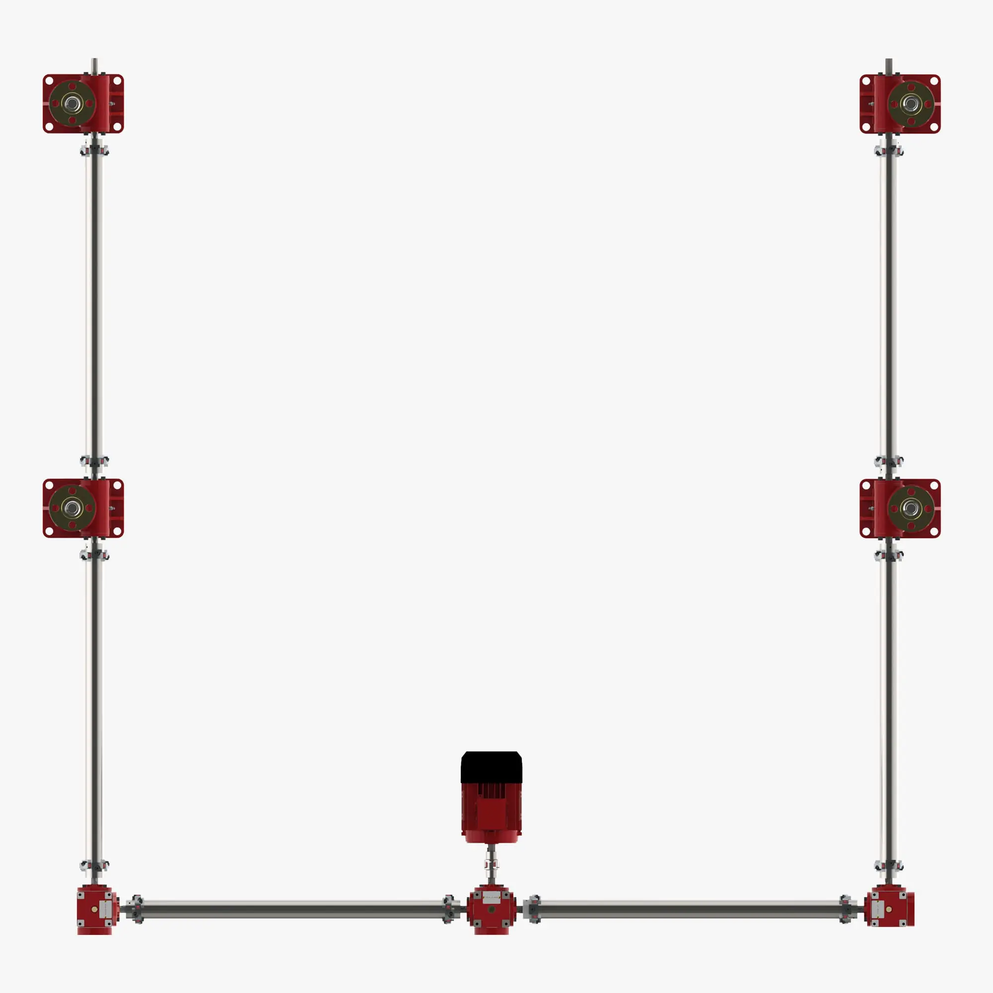
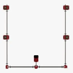
Die U-Konfiguration ist die ideale Anordnung, um Spindelhubelemente zusammen mit einem Antriebssystem zu bewegen, das um einen Umfang herumgeht.
Das System ist so angeordnet, dass die Spindelhubelemente und Antriebswellen dem Buchstaben U ähneln. Die primäre Antriebseinheit befindet sich an einem Ende des Systems in der Mitte einer Antriebslinie. Die Spindelhubelemente werden entlang der gegenüberliegenden "Beine" des Systems positioniert. Die häufigste Anzahl von Spindelhubgetrieben in einem System ist 4, es werden jedoch auch Systeme mit 6 bis 30 Spindelhubgetrieben angeboten.
Useful Information
System Parts List
The following parts list is for a U-configured system using 4 screw jacks. For systems with more screw jacks, increase the number of parts as required to complete the system.
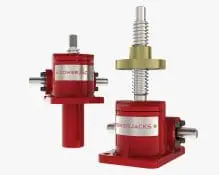
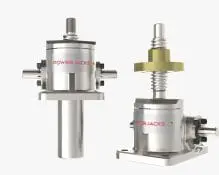
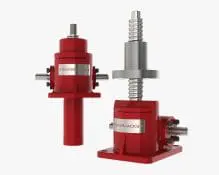
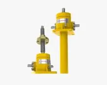
Screw Jacks x 4
– Select a screw jack type and size suitable for the application type (machine screw, ball screw, stainless steel or roller screw).
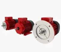
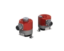
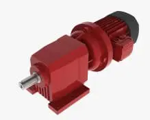
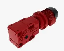
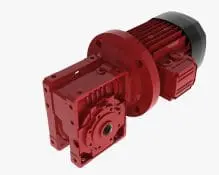
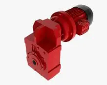
Primary Drive Unit x 1
– Bevel Gearbox with motor connected either by integral motor adaptor or separately mounted and coupled.
OR
– Geared motor (motorised reduction gearbox), typically a Helical Bevel, Parallel Shaft or Worm Gearbox.
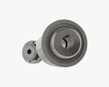
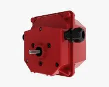
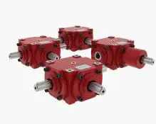
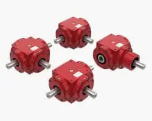
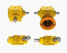
Side Gearboxes x 2
– Bevel gearboxes, typically Range-C with 1:1 gear ratio, 2-way solid shaft.
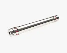
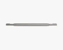
Drive Shafts
Select whether to use solid drive shafts with individual couplings on each and plummer block supports or self-supporting drive shafts (spacer couplings) that have integral couplings at each end and do not need extra support.
– Primary drive unit to side gearboxes x 2.
– Side gearbox to first screw jack x 2.
– Side screw jack to screw jack x 2.
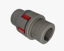
Couplings
Required if solid drive shafts used. Not required for self-supporting drive shafts (spacer couplings).
– 2 couplings for each drive shaft (1 at each end). Normally either Flexible Jaw Coupling or Steel Geared Flexible Coupling type depending on torque requirements. Typically 12 couplings in a 4 screw jack system.
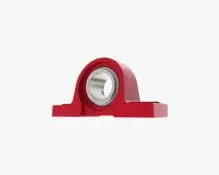
Plummer Blocks
Required if solid drive shafts used. Not required for self-supporting drive shafts (spacer couplings).
– All solid drive shafts need at least 2 plummer block supports (1 at each end). If the shaft is long then you may need more along the shaft length. Check drive shaft critical speed (shaft whirling).
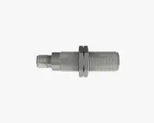
Limit Switches
End of stroke position limit switches are recommended as a minimum. Number required will depend on system control requirements.
– Rotary Cam Limit Switch. Normally mounted on one of the screw jacks in the system via an integrated adaptor.
– Proximity or electro-mechanical switches mounted on structure activity by a „target“ on the moving platform.
Encoders
Consider if you need position and speed feedback for the control system. Best location for an encoder is usually mounted on the end of the electric motor below the fan cowling. Supplied as an integrated unit. Both incremental and absolute encoders are available.
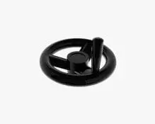
Rotation Indicator
If you need a visual indication of the system moving then a rotation indicator mounted on a screw jacks free worm shaft is a good option.
How a Jacking System Works
A screw jack system is where more than one screw jack is operated in unison to achieve a linear movement. The screw jack system arrangement is also commonly referred to as a “jacking system”.
The ability to mechanically link multiple screw jacks together so that they move in unison is one of their greatest advantages. Typical arrangements involve screw jacks, bevel gear boxes, motors, reduction gearboxes, drive shafts, couplings and plummer blocks.
Jacking Systems have 2 main features:
- They allow for the movement of large loads driven by a single motor e.g. 4 x ME18100 screw jacks arranged in a screw jack system could move a load of 400 Te (4000kN).
- Support loads evenly over a relatively large surface area e.g. 20Te load over a 24m2 area using four screw jacks with 6m x 4m centre spacing.
Typically jacking systems are mechanically linked between each driven item in the system. However electronically linked systems are also available. In these systems the screw jacks are individually motorised and synchronised via an electronic control system and closed feedback loop. This can also be expanded so that multiple mechanically linked jacking systems are synchronised / controlled electronically allowing linear motion solutions to be provided on a massive scale.
Jacking systems are regularly supplied to clients with 2, 4, 6, 8 screw jacks. Larger systems can extend up to 16 or higher. With the use of electronic synchronisation/control multiple systems or screw jacks can be used in unison. Extending the possible number of screw jacks used in unison in excess of 100.
This has allowed Power Jacks to provide jacking system solutions into most sectors. Production type environments whether in metal, civil, automotive, paper or energy are the main users of jacking systems however applications such as stadiums, communications and research also use jacking systems of small and large designs.
Whatever the application Power Jacks have the knowledge and experience that ensures the customers gets the best jacking system solution.
Verwandte Produkte
Downloads
Das komplette Angebot an Broschüren, Datenblättern, Videos und mehr finden Sie auf der Seite Downloads.
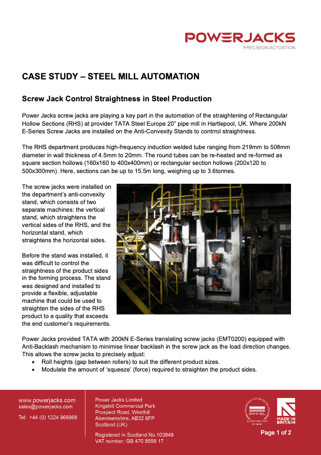
Case study showing use of screw jacks in the automation of a Steel Mill Anti Convexity Stand.
Steel Mill Anti Convexity Stand Automation(EN)
Positioning solutions for anode beams in all types of aluminium reduction cell technology.
Aluminium Positioning Solutions(EN)
Power Jacks profile detailed through our proposition, expertise, performance, people, precision, principles and pledge.
Company Profile(EN)

When there can be no compromise on performance, safety, quality, reliability and durability. Trust power jacks engineered solutions for the most demanding nuclear applications.
Lifting & Positioning Solutions for the Nuclear Industry(EN)

A global reach with a local service, we work closely with our customers to ensure the best solution for all their clean and precise Electro-Mechanical solutions for subsea, offshore and onshore applications.
Oil & Gas Industry Lifting & Positioning Solutions(EN)
Overview of lifting & positioning product portfolio. Includes Screw Jacks, Linear Actuators, Bevel Gearboxes & Screw Jack Systems.