Couplings & Drive Shafts
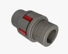
Flexible Spacer Coupling
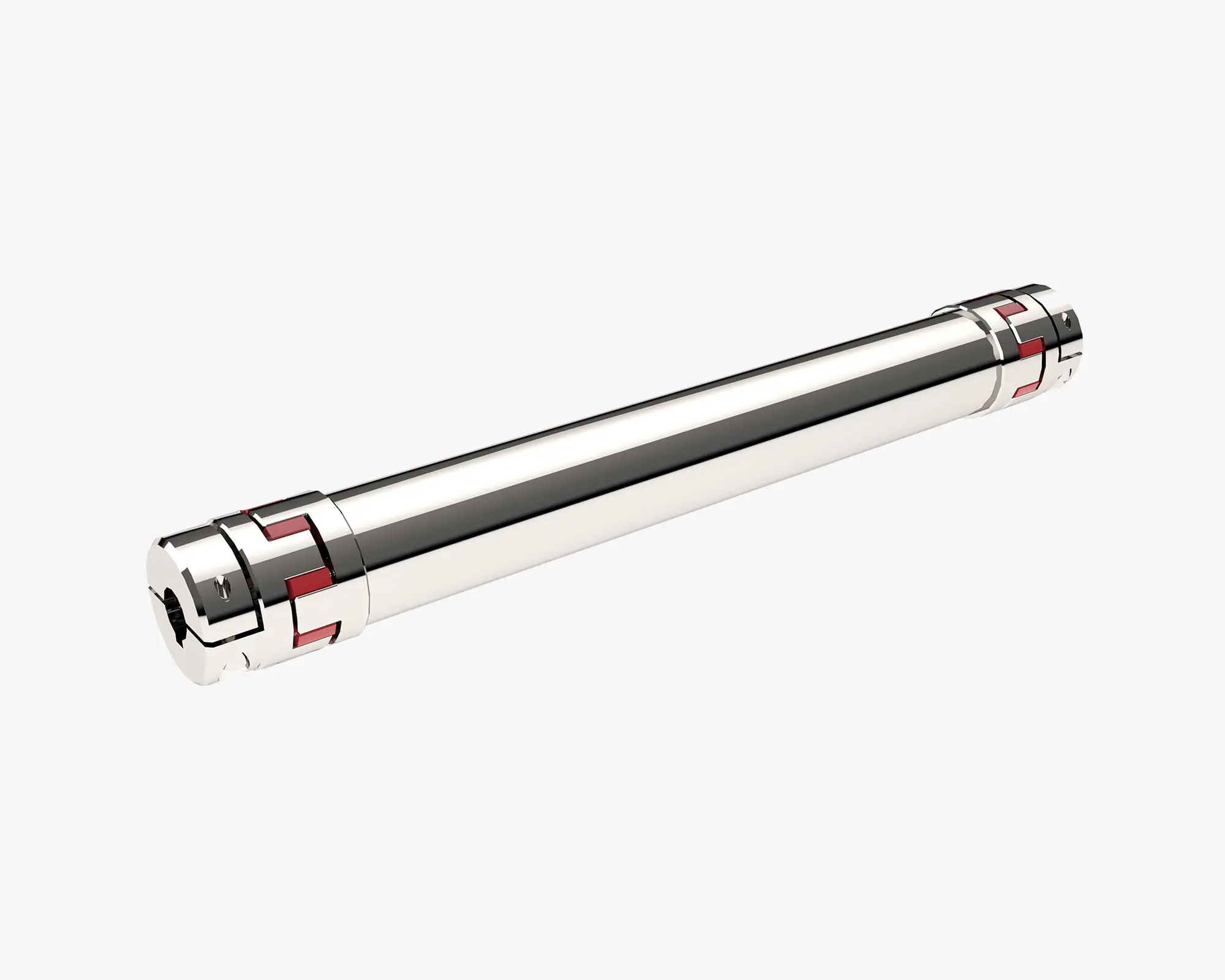
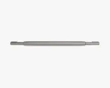
Spacer Couplings with Jaw Coupling Hubs are self-supporting drive shafts with flexible couplings at each end for low to medium torque transmission without the need for bearing shaft supports.
Available in 7 sizes for torque up to 525Nm for shaft lengths up to 4m as standard. Aluminium construction with steel and stainless steel versions on request.
Useful Information
Key Features
- Self-Supporting Drive Shaft, know as Spacer Coupling
- Standard has “split coupling hub” allowing shaft installation after other system components in place. Also easy replacement.
- Torque Ratings up to 525Nm
- 7 Sizes
- Hub bore sizes up to 60mm
- Compact, light, robust, safe operation, long life
- Two identical hubs and one flexible elastomeric element at each end
- Hubs of high strength aluminium
- Standard hub is split hub with clamp and keyway drive grip
- 3 elastomeric spider elements 92 Shore is standard with 98 and 86 available on request
- Damps vibrations and shocks, compensates for axial, radial and angular misalignment
Selecting the Right Spacer Coupling
The selection of spacer coupling type depends on the installation and the type of misalignment. The three main types of misalignment encountered are:-
– Angular Misalignment is usually present to some extent on all applications, typical values 1° – 2°. Sometimes higher values are necessary
– Parallel (Radial) Misalignment is also nearly always present. A well aligned installation might have values below 0.25 mm
– Axial Misalignment (End Float) sometimes caused by thermal expansion or as a result of machine design
Other considerations include:
– Backlash Free Couplings are either one part couplings, special jaw arrangement, disc couplings or have bolted joints. These are effective for precise positioning and to avoid wear on reversing drives.
– Torsional rigidity of couplings depends on the joining method. Types with rubber or plastic elements can be considered as torsionally soft and will have an amount of twist at rated torque.
– Check for shaft critical speed (shaft whirling). A chart is provided in the screw jack design guide for permissible shaft speed against shaft length for the standard spacer coupling sizes.
Procedure:
– Decide if the coupling should be torsionally soft or rigid.
– Consider whether a small amount of backlash is acceptable.
– Calculate the required coupling torque.
– Make a provisional selection.
– Check that the spacer coupling’s maximum speed is permissible.
– Check that the coupling’s dimensions are acceptable.
Notes:
– Maximum misalignment values are extremes and should not be combined. As operating misalignment approaches the maximum, torque and power ratings should be reduced to maintain life
– The maximum axial misalignment values apply when the coupling is aligned. If axial misalignment greater than the listed maximum is required, consult Power Jacks
– The inertia values includes shafts through the bores
– When ordering please quote the spacer coupling size and type, specify the bore and keyway sizes, specify the shaft length (“DBSE” dimension) and advise if hub puller holes or set-screws are required
– For maximum performance the screw jacks, actuators, gearboxes, motors and shafts should be carefully aligned
– Imperial (Inch) couplings on request
Contact Power Jacks with your order or technical enquiry