
顶升系统
U 型配置
CAD 和宣传册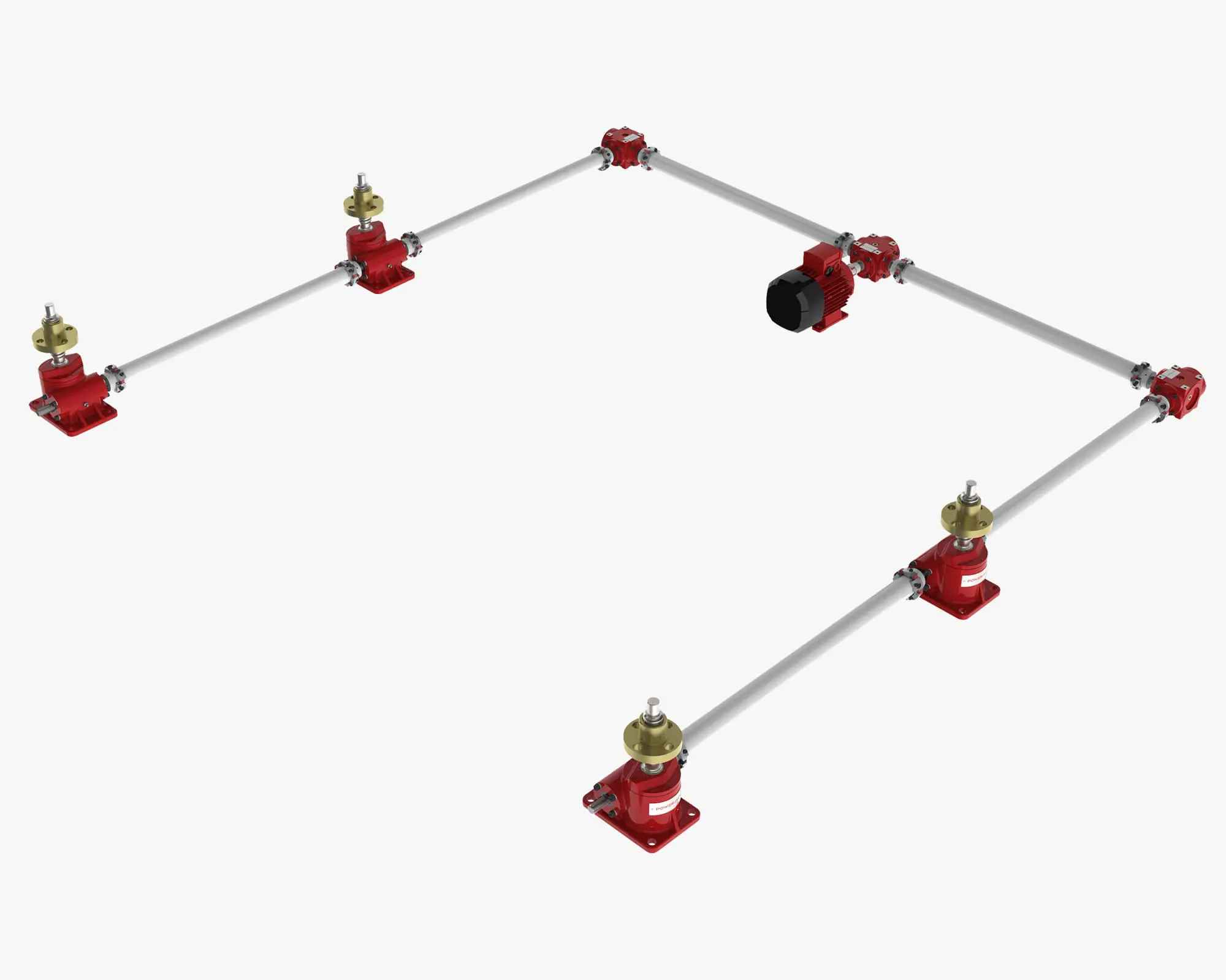
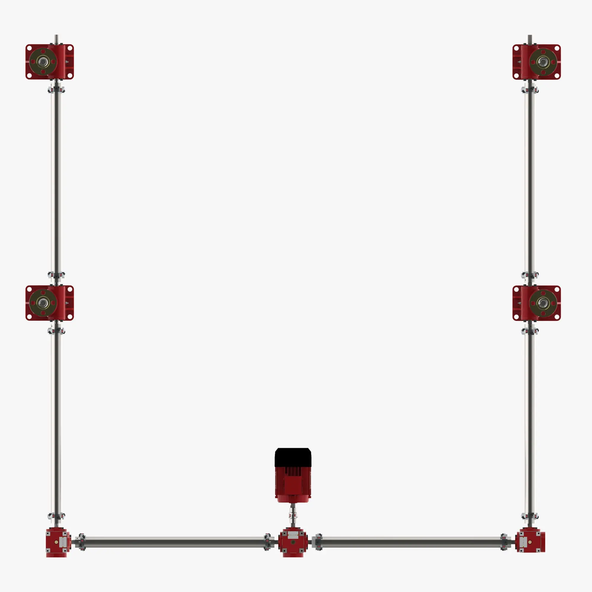
U 型配置顶升系统 顶升系统是一种理想的布置方式,可将螺旋升降机与环绕周边的驱动系统一起移动。
系统中螺旋升降机和传动轴的排列方式类似于字母 U,主驱动装置位于系统的一端,处于传动线的中间。螺旋升降机沿系统相对的 "腿 "布置。系统中最常见的螺旋升降机数量为 4 个,但也有使用 6 至 30 个螺旋升降机的系统。
实用信息
系统部件清单
以下零件清单适用于使用 4 个螺旋升降机的 U 型配置系统。对于使用更多螺旋升降机的系统,请根据需要增加零件数量,以完成系统。
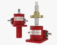
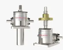
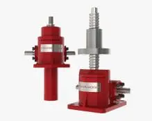
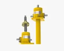
螺旋升降机 x 4
- 选择适合应用类型的螺旋升降机类型和尺寸(机器螺旋升降机、滚珠螺旋升降机、不锈钢螺旋升降机或滚柱螺旋升降机)。
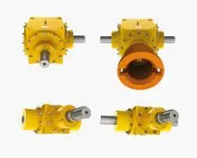
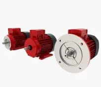
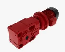
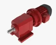
主驱动装置 x 1
- 锥齿轮箱与电机通过内置电机适配器连接,或单独安装和耦合。
或
- 齿轮电机(电动减速箱),通常为锥齿轮箱、平行轴箱或蜗轮箱。
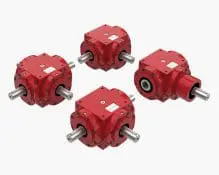
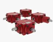
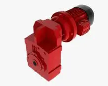
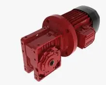
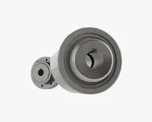
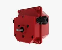
侧齿轮箱 x 2
- 锥齿轮箱,通常为范围 C,齿轮比为 1:1,双向实心轴。
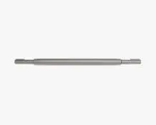
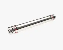
传动轴
选择是使用每端都有单独联轴器和梅花块支撑的实心传动轴,还是使用每端都有整体联轴器且不需要额外支撑的自支撑传动轴(隔板联轴器)。
- 主传动装置至侧齿轮箱 x 2。
- 侧齿轮箱至第一螺旋升降机 x 2。
- 侧螺旋升降机至螺旋升降机 x 2。
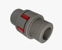
联轴器
使用实心传动轴时需要。自支撑传动轴(间隔联轴器)不需要。
- 每个传动轴 2 个联轴器(两端各 1 个)。通常为弹性颚式联轴器或钢齿轮弹性联轴器,取决于扭矩要求。4 螺旋升降机系统中通常有 12 个联轴器。
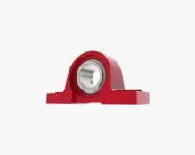
Plummer 块
使用实心传动轴时需要。自支撑传动轴(间隔联轴器)不需要。
- 所有实心传动轴都需要至少两个梅花块支撑(两端各一个)。如果传动轴较长,则可能需要沿轴的长度方向安装更多。检查传动轴临界转速(轴旋转)。
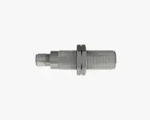
限位开关
建议至少使用冲程终点位置限位开关。所需数量取决于系统控制要求。
- 旋转凸轮限位开关。通常通过集成适配器安装在系统中的一个螺旋升降机上。
- 通过移动平台上的 “目标”,在结构上安装接近开关或机电开关。
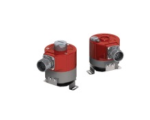
编码器
考虑控制系统是否需要位置和速度反馈。编码器的最佳位置通常是安装在风扇罩下方的电机末端。作为一个集成单元提供。可提供增量式和绝对式编码器。
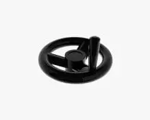
旋转指示器
如果需要直观地显示系统的运动情况,那么安装在螺旋升降机自由蜗杆轴上的旋转指示器是一个不错的选择。
顶升系统的工作原理
螺旋升降机系统是指多个螺旋升降机同时运行,以实现直线运动。螺旋升降机系统布置通常也被称为 “顶升系统”。
能够将多个螺旋升降机机械地连接在一起,使其同步运动,是螺旋升降机的最大优势之一。典型的布置方式包括螺旋升降机、锥齿轮箱、电机、减速箱、传动轴、联轴器和梅花块。
顶升系统有 2 个主要特点:
- 例如,4 x ME18100 螺旋升降机组成的螺旋升降机系统可移动 400 Te(4000 千牛)的载荷。
- 在相对较大的面积上均匀承重,例如,在 24 平方米的面积上承重 20 吨,使用四个螺旋升降机,中心间距为 6 米 x 4 米。
通常情况下,顶升系统中每个被驱动项目之间都采用机械连接。但也有电子连接的系统。在这些系统中,螺旋升降机通过电子控制系统和闭合反馈回路单独电动和同步。这种系统还可以扩展,使多个机械连接的顶升系统通过电子方式同步/控制,从而提供大规模的线性运动解决方案。
顶升系统定期向客户提供 2、4、6、8 螺旋升降机。更大的系统可以扩展到 16 个或更多。通过使用电子同步/控制,多个系统或螺旋升降机可以同时使用。可同时使用的螺旋升降机数量超过 100 台。
这使得 Power Jacks 能够为大多数行业提供顶升系统解决方案。金属、土木、汽车、造纸或能源等生产型环境是顶升系统的主要用户,但体育场馆、通信和研究等应用领域也在使用各种大小设计的顶升系统。
无论何种应用,Power Jacks 都拥有丰富的知识和经验,确保客户获得最佳的顶升系统解决方案。
下载
如需完整的产品手册、数据表、视频等,请访问下载页面。
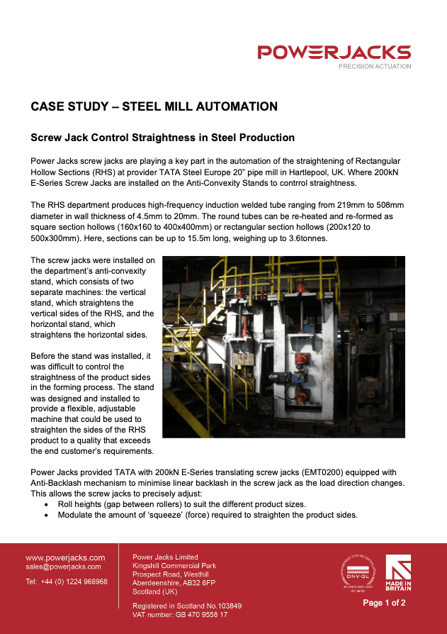
展示螺旋升降机在钢厂防凸起机架自动化中应用的案例研究。
钢厂防凸起机架自动化(EN)
所有类型铝还原电池技术中阳极束的定位解决方案。
铝定位解决方案(EN)
Power Jacks 简介详细介绍了我们的主张、专长、业绩、员工、精确度、原则和承诺。
公司简介(中文)
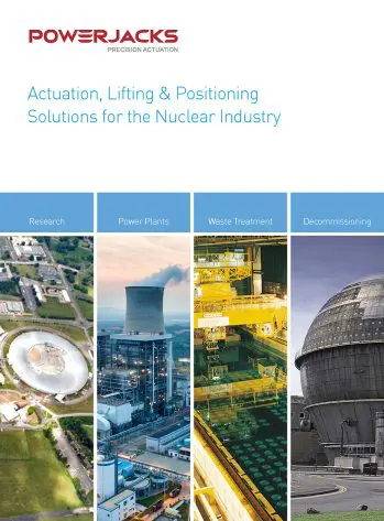
在性能、安全、质量、可靠性和耐用性方面,我们绝不妥协。为最苛刻的核能应用提供解决方案的动力千斤顶值得信赖。
核工业提升和定位解决方案(EN)

我们的服务遍布全球,并提供本地化服务,我们与客户密切合作,确保为客户提供最佳解决方案,为海底、近海和陆上应用提供清洁、精确的机电解决方案。
石油与天然气行业提升与定位解决方案(EN)
起重和定位产品组合概览。包括螺旋升降机、直线执行器、锥齿轮箱和螺旋升降机系统。